🎨 Drawing
The objective of this frame is to allow the user to design their own platform by dragging and dropping components onto the canvas.
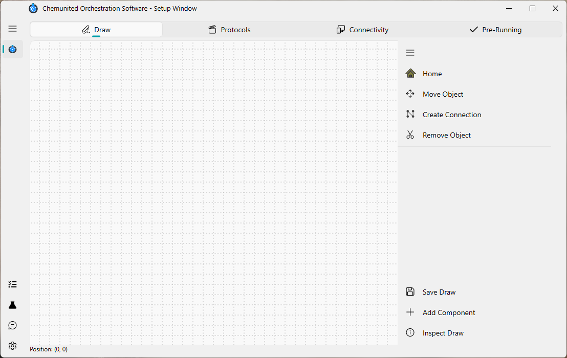
Below is a description of the main tools available in this window:
 Home
Home
Centers the drawing on the canvas. This is useful for reorienting the view and exploring your setup more easily.
 Move Object
Activates the mode to move components or connections within the drawing area.
 Create Connection
Enables the connection mode, allowing you to build connections between components.
 Remove Object
Allows the removal of selected components or existing connections from the drawing.
 Save Draw
Saves all modifications made to the current project file.
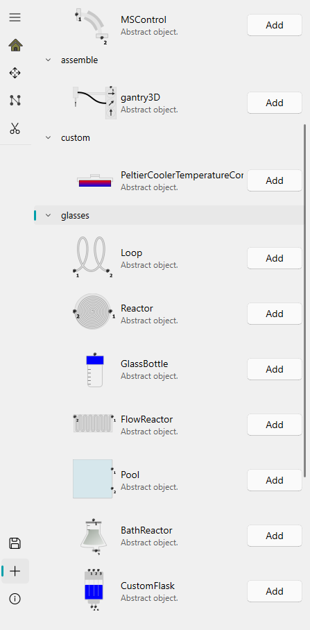
- Add Component
Opens the component library, from which you can add new electronic elements or utensils to the setup.
 Inspect Draw
This mode helps you inspect the properties of components. While you can double-click any component to open its properties, this mode also brings all components to the front of the drawing to make inspection easier.
To view or edit the properties of a connection, activate Inspect Draw mode and click on the inflexion points of the connection to display its parameters.
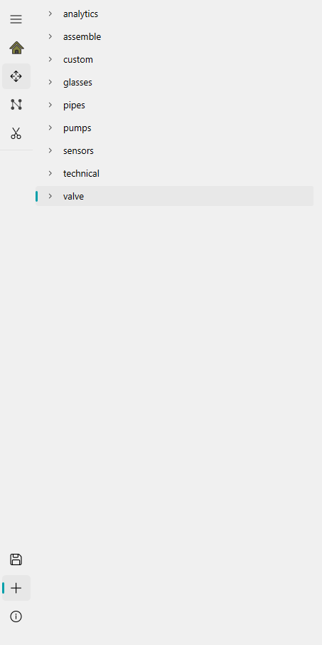
Component available
This panel lists all components available for building your setup, organized into categories.
Connections
Connections define how components interact within the setup. Each connection begins and ends at a connection point, and each point belongs to a specific category. Only connection points of the same category can be linked.
Types of Connection Points
There are four standardized connection point types:
 Flow Connection Point
Represents standard connections used for tubing that transports fluids through the system.
 Heat Connection Point
Used for defining heat-transfer relationships between components during simulation. These connections affect simulated thermal behavior, but they do not influence the execution of the real protocol.
 Electronic Connection Point
Used for connections that transmit electronic control signals. While devices in ChemUnited can be accessed directly, in certain cases, it is more efficient to trigger device actions through the microcontroller connected to it. This is especially useful when several devices must be activated simultaneously. For more details on the microcontroller implementation, see the referenced documentation.
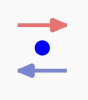
 Movement Connection Point
An extension of the flow connection, used to represent the movement of samples—typically handled by mechanical arms, gantries, or other robotic modules.
A connection can only be established between points of the same type (Flow–Flow, Heat–Heat, Electronic–Electronic, or Movement–Movement).
Components & connections properties
After adding a component, a window will appear where the user can provide the component’s details. The most important field is the name, which serves as the unique identifier for accessing the component throughout the entire project.
Choose the component name carefully. All properties, protocols, and orchestration features are linked to this name. If you need to rename a component later, the recommended approach is to remove and recreate it again using the new name.
Unlike components, connection properties do not open automatically.
While all components share some common parameters, each one also includes specific adjustable settings depending on its type.
More details about each component can be found in the reference section: Components Available.